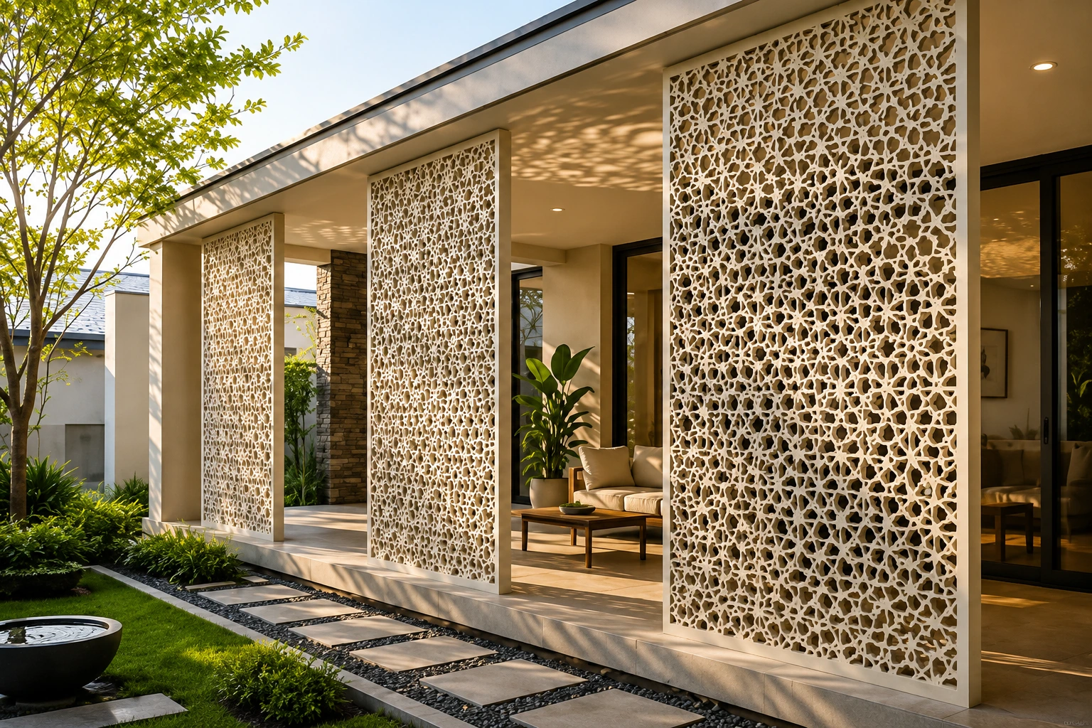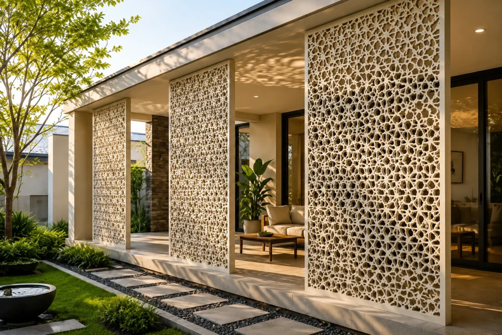
A GRC panel is a thin-section cladding element, typically a 10 to 15 mm skin of glassfibre reinforced concrete, fixed back to a building’s structure with dedicated gravity and restraint anchors. It carries its own weight and wind load, nothing else. Panel area ranges from a few square metres up to around 20, depending on the type.
That definition contains the whole design problem. A panel that thin, that large, made of a cementitious material that moves with temperature and moisture, hung off a frame that moves independently, has to be detailed so the movement goes into the joints rather than into the panel.
Get that right and GRC panels last for decades. Get it wrong and you get cracks along the fixing lines within two monsoons.
The four panel types
| GRC Panel Type | Construction | Typical Max Area | Use |
| Single Skin | 10–15 mm skin, flat or ribbed | Small to moderate | Feature cladding, soffits, fascias |
| Stud Frame | GRC skin on steel frame with flex + gravity anchors | 10–20 m² | Large-format façade cladding |
| Sandwich | Two GRC skins with insulating core | 6.5 m² | Insulated wall panels |
| Permanent Formwork | GRC used as a stay-in-place shutter | Varies | Column encasement, complex in-situ geometry |
The area figures are the ones to notice. A stud-frame panel can run to 20 square metres; a sandwich panel is recommended to stop at 6.5. That is not a manufacturing limitation, it is a physics one — two skins at different temperatures and different moisture contents want to bow relative to each other, and the larger the panel the greater the resulting deflection and stress. If someone offers you a 12 square metre insulated sandwich panel, ask what analysis supports it.
Single-skin panels are often ribbed with integral stiffening rather than made thicker. A rib adds section depth where it is needed for bending without adding weight across the whole face, which is the same logic as a beam flange. Overall panel depth including ribs and returns commonly runs well beyond the nominal skin thickness — EPD data for ribbed GRC panels declares 15 to 75 mm overall — so a “15 mm panel” and a 15 mm build-up are not the same thing.
What decides the type
Three things, in this order.
Span and wind load. Facade panels are designed against IS 875 Part 3:2015 in India, and the governing figure is the local external pressure coefficient rather than the global one. Corners, edges and parapets see substantially higher local pressures than the body of an elevation. A single panel specification applied uniformly across a whole facade is a sign that the local coefficients have not been checked.
Whether the panel is doing thermal work. If it is just a rainscreen with insulation behind it in the wall build-up, single skin or stud frame. If the panel itself is the insulated element, sandwich — with the area penalty above.
Geometry. Deep relief, undercuts and compound curvature push toward premix casting, which limits achievable strength. Flat and gently curved large-format work suits spray, which gives the higher grades. This matters because manufacturing method sets the available strength.
Sprayed GRC at 4.0 to 5.5% fibre by weight reaches a Modulus of Rupture of 18 to 30 MPa. Premix vibration-cast GRC at 2.0 to 3.5% fibre reaches 5 to 14 MPa. Characteristic GRCA values for Grade 18 are a Limit of Proportionality of 7 MPa and an MOR of 18 MPa; Grade 8 gives 5 and 8. You cannot specify an intricate premix-cast profile and then design it to sprayed Grade 18 values. That mismatch is one of the more common errors in GRC tender documents.
Fixings: two jobs, never confused
The load path is the part of GRC panel design that most rewards attention, and it is conceptually simple once stated.
Every panel needs gravity fixings, which carry its self-weight, and restraint fixings, which resist wind pressure and suction. The two are not interchangeable. Gravity fixings establish one fixed locator point, from which the panel is allowed to expand and contract. Restraint fixings must slide, because their job is to hold the panel against wind while permitting it to move in plane.
Four fixing families are in use: encapsulated fixings, where threaded sockets are cast into thickened GRC bosses; bonded fixings, where flex and gravity anchors sit on adhesive pads bonded to the rear of the skin; face fixings, visible on the outer surface; and concealed slot-and-dowel arrangements.
The failure mode when this goes wrong is predictable. If restraint fixings are installed tight rather than sliding, or if the slot clearance is taken up during installation, the panel is restrained at multiple points and any movement has to be absorbed by the material. Thin-section cement absorbs movement by cracking.
The number that governs everything: 1 to 1.5 mm per metre
The GRCA design guidance is explicit that an allowance of 1 to 1.5 mm per metre of product dimension must be accommodated in joint design and fixing movement.
Work that through. A three-metre panel needs three to four and a half millimetres of movement capacity. If the joint is detailed at 6 mm and the fixing slots give 3 mm of travel, that works. If the joint is closed up to 3 mm on site because the panel above was set low, it does not.
The underlying properties driving that figure:
| Property | Value |
| Coefficient of Thermal Expansion | 10–20 × 10⁻⁶ per °C |
| Ultimate Drying Shrinkage | Up to 0.2%, mix-dependent |
| AR Glass Fibre Elastic Modulus | 72–74 GN/m² |
| Restrained Shrinkage Stress | 0.5–1.8 N/mm² (full restraint, external) |
| Thermal Stress | 0.2–2.5 N/mm², depending on gradient |
Compare those stress values against a Grade 8 LOP of 5 MPa and the arithmetic becomes uncomfortable: fully restrained shrinkage plus a thermal gradient can consume a substantial fraction of the material’s cracking threshold before any wind load arrives. Movement joints are not a detailing preference. They are what keeps the panel inside its elastic range.
Delhi NCR makes this more acute than a temperate climate would. A facade panel in Gurugram experiences a large annual temperature swing, intense summer surface heating, and a sharp moisture transition at monsoon onset. The movement is real and it is cyclical.
The standards to name, and the one that does not exist
There is no BIS or IS standard for GRC. The relevant BIS committee’s fibre-cement standards — IS 14862:2000 for flat sheets and IS 14871:2000 for corrugated roofing and cladding sheets — do not cover it, and IS 18256:2023 covers glassfibre reinforced polymer reinforcing bar, which is a different material entirely and is regularly confused with GRC in specifications.
So an Indian GRC specification has to name the international framework explicitly:
– The International GRCA specification for the manufacture, curing and testing of GRC products
– EN 1169:2024: factory production control
– EN 1170:2024: test methods, now consolidated into a single document covering bending strength, water absorption and dry density, moisture movement, and a cyclic ageing type test
– EN 15191:2024: classification of GRC performance
The edition dates matter more than usual right now. All three were revised in 2024 and the previous editions — EN 1169:1999, the EN 1170 parts from 1998 and 2008, and EN 15191:2009 — are withdrawn. Many GRC specification documents in circulation, including some published as recently as 2021, still cite the superseded versions. A tender that references EN 1170-5:1998 is referencing a standard that no longer exists.
One caution on what these standards do and do not cover. Writing on the European standardisation of GRC for a GRCA congress, Hervé Beinish of CERIB, Secretary of the CEN committee working group responsible, and Peter Curiger of Stahlton Bauteile noted that EN 15191 “applies only if EN 1169 is followed” and that the standard “does not include the design methods.”
Production control and classification are one thing; structural design is another. Design comes from the GRCA design guide working in limit state theory, and it must use aged material values rather than 28-day test results, because GRC’s ultimate bending strength declines over decades as the material embrittles. Panels from a 1974 London building designed for a 25-year life showed roughly a 50% reduction in MOR after 28 years. The expected loss is defined in EN 15191. Ask whether your panels were designed on aged values — it is a question that separates competent GRC engineering from optimistic engineering.
What goes wrong, and what prevents it
| Failure | Cause | Prevention |
| Cracking at fixing lines | Restrained movement, slots taken up | Sliding restraints, one fixed locator, joint width per the 1–1.5 mm/m rule |
| Surface crazing | Shrinkage of the cement-rich surface | Polymer modification; controlled curing (7 days at 20 °C and 95% RH for non-polymer grades) |
| Efflorescence | Soluble salts migrating with water | Polymer modification limits salt migration; surface treatment |
| Thermal bowing | Differential temperature and moisture across a two-skin section | Respect the 6.5 m² sandwich limit; analyse anything larger |
| Fixing corrosion | Dissimilar metals in contact, chlorides | Isolation sleeves and separators; specified stainless grade; verified coating thickness |
| Staining and streaking | Uncontrolled water run-off across the face | Drips, throats, weep paths and baffles detailed and kept clear |
| Colour variation | Cement, pigment and sand lot variation; differing cure and demould ages | Single cement source, batched pigment, sequenced panels, approved control samples |
Samples
The last row is trade practice rather than a documented standard requirement, but it is the one clients notice first. Colour consistency on a large elevation is a production discipline question, and the right time to address it is at control-sample approval, not after installation.
Installation checks worth writing into the method statement
These are the ones that determine whether the design intent survives contact with the site.
1. One gravity locator fixed per panel; every restraint fixing sliding and centred in its slot.
2. Washer clearance to slot ends at least 3 mm with the fixing at mid-position.
3. Joint widths within ±3 mm of the drawing, checked as installation proceeds rather than at the end.
4. Closed-cell backer rod compressed by roughly 25% before sealant application.
5. Anchor torque within ±10% of specification, recorded.
6. Isolation maintained between dissimilar metals and between metal and concrete, using approved separators or sleeves.
7. Drainage and weep paths unobstructed, baffles in place.
Six of those seven are things an inspector can verify in minutes and that become expensive to correct once the facade is complete.
Common questions
The GRC skin is commonly 10 to 15 mm. Overall panel depth is greater where ribs, returns, a backing frame or an insulating core are included — published data for ribbed panels runs from 15 to 75 mm overall.
Stud-frame panels are commonly made up to 10 to 20 square metres. Sandwich panels are recommended to stay at or below 6.5 square metres because of thermal bowing.
Through separate gravity fixings that carry weight and restraint fixings that resist wind and must be free to slide. Fixing types include encapsulated sockets, bonded flex and gravity anchors, face fixings and concealed slot-and-dowel systems.
They crack when movement is restrained. The material needs 1 to 1.5 mm of movement capacity per metre of panel dimension; if the joints and fixing slots do not provide it, the panel accommodates the movement by cracking.
There is no Indian standard for GRC. Specify the GRCA specification with EN 1169:2024, EN 1170:2024 and EN 15191:2024, and use IS 875 Part 3:2015 for wind loading, IS 15916:2020 for prefabricated concrete erection and IS 456 for the supporting structure.
Single skin is a thin GRC shell, sometimes ribbed. Stud frame carries that shell on a steel backing frame, allowing much larger panels. Sandwich bonds two skins to an insulating core, which makes the panel itself thermally useful but limits its area.
Getting a panel specification right
The most useful thing you can do at tender stage is settle the fixing strategy, because it determines panel size, joint layout and the design of the supporting structure — and changing it later means changing all three.
For a project in Delhi NCR, Mahesh GRC’s team in Gurugram can work through panel typology, grade and casting method, movement joint layout and fixing design against your elevation and wind exposure, and supply the test documentation the specification calls for.
This article is general technical information for architects, engineers and specifiers, not a design document. Panel sizes, material properties and fixing capacities vary between manufacturers and production methods. Structural design of cladding panels and their fixings must be carried out by a qualified engineer against project-specific loading. Standards are cited as at August 2026 and are periodically revised; verify current editions before writing a specification.